Optical Tweezers: a comprehensive tutorial
Learn about optical tweezers, their principles, applications in biology, instrumentation, advanced techniques, and detection strategies.
Introduction to Optical Tweezers.
Optical tweezers are highly focused laser beams that can trap and manipulate microscopic particles, such as beads, biological cells, and even molecules, with incredible precision. Developed in the 1980s, this powerful technique has become an essential tool in various scientific fields, particularly biology and physics.
Historical background.
The concept of optical trapping was introduced in the early 1970s by Arthur Ashkin at Bell Labs. Ashkin demonstrated that laser light could exert enough force to move and trap small particles. His research in the late 1980s led to the development of optical tweezers, a refined version of optical traps. By 1987, Ashkin successfully used highly focused laser beams to manipulate biological samples. In recognition of his pioneering work, Arthur Ashkin was awarded the Nobel Prize in Physics in 2018 for the optical tweezers and their application to biological systems.
How Optical Tweezers work
Optical tweezers operate based on the principles of light momentum transfer. When a laser beam is focused through a high numerical aperture (NA) lens, it creates a strong electric field gradient. This gradient exerts a force on dielectric particles, drawing them towards the region of highest intensity, typically the focal point of the laser beam.
Key forces involved
- Gradient Force: This attractive force pulls particles towards the beam’s center, where the light intensity is highest. It is crucial for stable trapping and is dominant in high NA systems.
- Scattering Force: This force pushes particles along the direction of light propagation. It is generally balanced by the gradient force to maintain stable trapping.
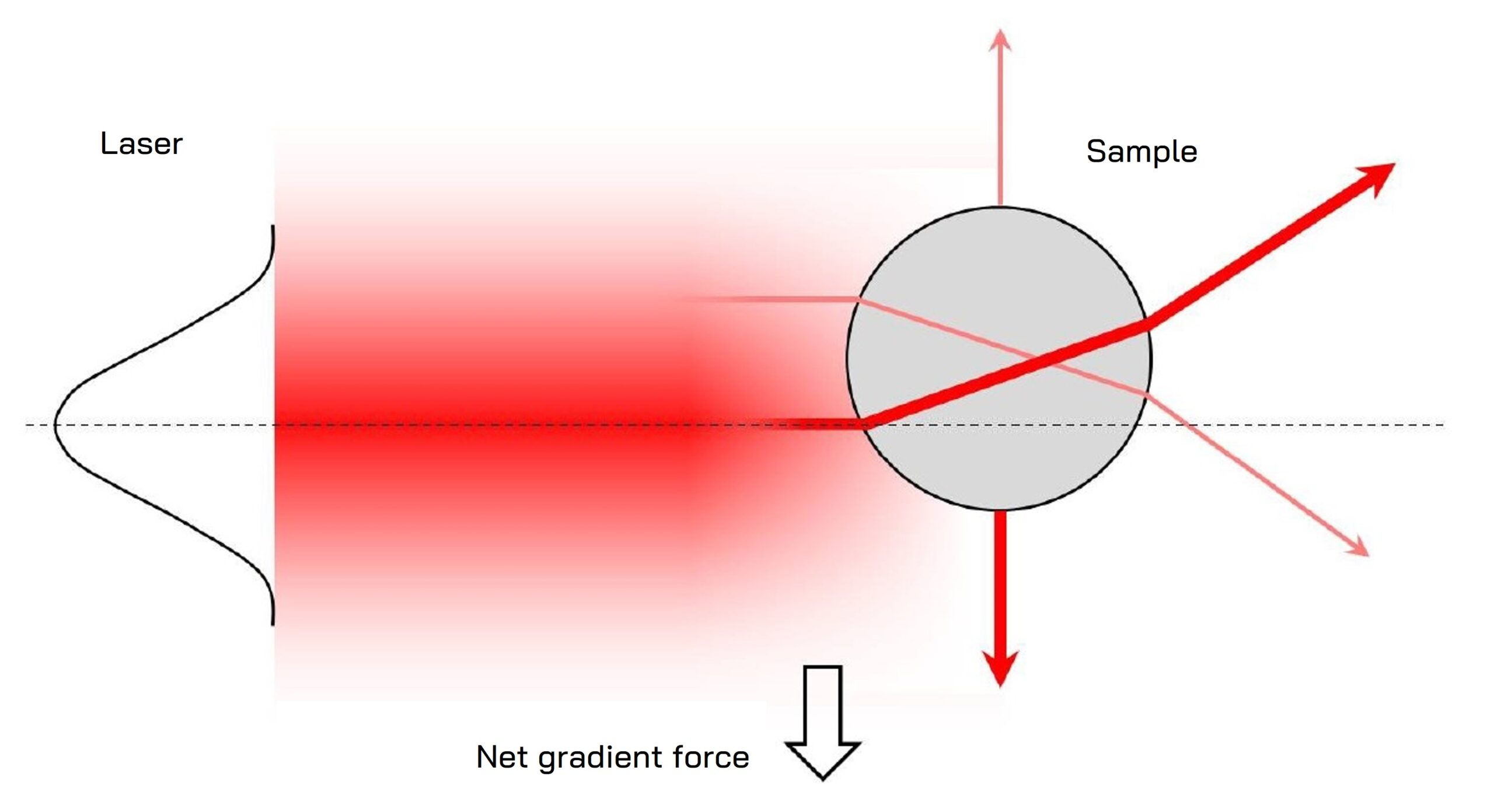
Diagram showing the principle of gradient force generation in optical tweezers for a trapped particle.
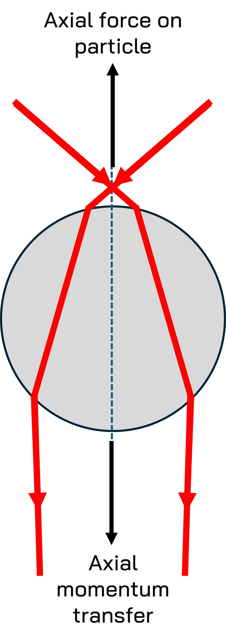
Diagram showing the principle of momentum transfer in the axial direction
Applications in Biology.
Optical tweezers have revolutionized biological research by enabling the precise manipulation of cells, organelles, and single molecules. Significant milestones include:
Manipulation of biological samples.
Ashkin’s early experiments demonstrated the ability to trap and manipulate bacteria and other small biological entities.
Single Molecule and Cell Biophysics.
Optical tweezers have been instrumental in studying single-molecule dynamics of DNA, proteins, and other macromolecules, offering valuable insights into molecular interactions and cellular processes. Recently, this technology has advanced to enable the study of cellular forces and the mechanical characterization of cells and tissues. Cell Biophysics applications include cell membrane mechanics, intracellular rheology, cell-cell interaction forces, cell motion forces, or liquid-liquid phase separation (LLPS) of protein droplets. Click here for a detailed explanation of these applications.
Applications in other fields: Physical Sciences
Physical sciences are also a promising field of application of optical tweezers in diverse areas such as atom cooling, quantum computing or colloidal and liquid crystal physics.
Instrumentation.
An optical tweezers setup typically consists of the following components:
Laser source
A highly focused laser beam, usually in the infrared spectrum, is used for trapping.
High-NA objective lens
This lens focuses the laser beam to a diffraction-limited spot, creating a strong electric field gradient.
Microscope
Often integrated into the setup to visualize the trapped particles and facilitate precise manipulation.
Detection system
Used to monitor the position and movement of trapped particles, often employing cameras or photodetectors.
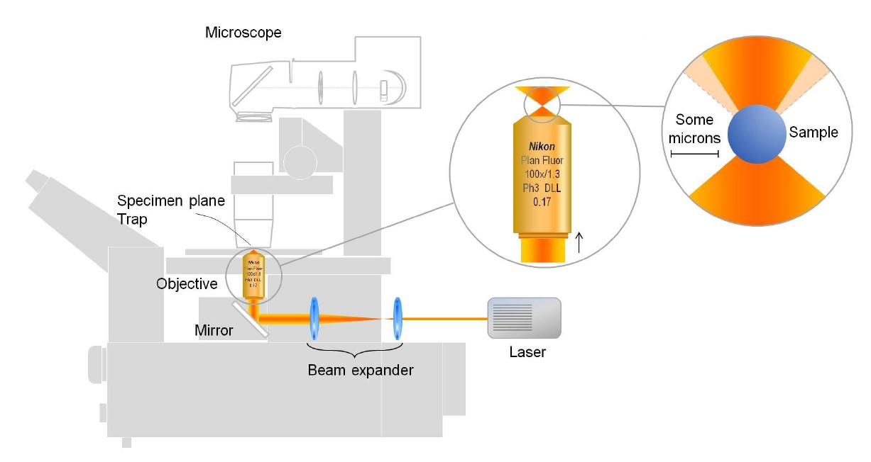
Diagram of a basic optical tweezers setup with a single fixed trap.
Beam steering technologies for Optical Tweezers.
While a simple setup like the one depicted in the previous figure can be used to trap microscopic objects in a static way, more complex schemes need to be implemented when sample manipulation is desired. Several beam steering techniques of different complexity allow manipulating one or multiple optical traps, each one with its own advantages and limitations. These are some popular options:
Acousto-optic deflectors (AODs).
These devices use sound waves to diffract and steer the laser beam, allowing rapid and precise movement of multiple optical traps by means of the time-sharing technique. A single pair of AODs can generate multiple traps and manipulate them independently .
Advantages | Limitations |
| Highest beam steering speed, precision and repeatability | Limited deflection angle |
| Dynamic control of multiple traps | Diffraction efficiency of 65-70%. |
| Measuring forces on multiple traps | |
| No mechanical parts involved |
Mirror based deflectors (Galvo Mirrors, MEMs)
These mirrors, controlled by electrical currents, steer the laser beam by adjusting the mirror angle. Due to their limited speed, such devices are not used for mutliple time-shared trap generation. Each individual trap requires its own XY mirror.
Advantages | Limitations |
| Good angular range of beam steering | Limited speed for fast dynamic trapping applications |
| Good reflection efficiency >90% | Slow response time |
| Lower accuracy than AODs | |
| Sensitive to mechanical noise |
Spatial light modulators (SLMs)
SLMs modulate the phase of the laser beam across its profile, creating multiple traps and moving them by changing the phase pattern. Each trap from the hologram set can be moved independently but measuring forces on each individual trap is not possible with advanced BFPI techniques.
Advantages | Limitations |
| Dynamic holographic control of multiple traps | Relatively slower update rates |
| High flexibility in beam shaping | Higher computational requirements |
| Limited capability for measuring forces on a single trap of a multiple set |
Microscope stage movement
The sample stage can be precisely moved using piezoelectric or motorized stages, adjusting the relative position of the optical trap to the sample. This approach is typically used with low-cost single fixed trap setups. However, it can be combined with other beam steering techniques.
Advantages | Limitations |
| Large-scale movement across sample | Slower compared to other methods |
| No optical efficiency limitation | Limited precision unless piezoelectric stages are used |
| Limited dynamic control |
Advanced techniques for multiple traps dynamic control.
The following techniques are the two standard approaches for systems generating multiple traps (tens to hundreds of independent traps)
Holographic optical tweezers
Using spatial light modulators or AODs in combination with computer-generated holograms, multiple traps can be created and dynamically controlled. However, all traps are permanent and thus indistinguishable to BFPI-based force detectors. Simultaneous force measurements from multiple traps are only possible with lower-throughput force measurement techniques such as video tracking and therefore with rather limited accuracy and temporal resolution.
Time-shared optical tweezers
Using high-speed steering devices such as AODs, multiple traps can be created and controlled by rapidly switching the trapping laser position over the sample plane. Proper synchronization with a BFPI based detection device allows advanced force measurements simultaneously on multiple traps with high temporal resolution and accuracy. See and example of this technique being used to generate complex trap dynamics.
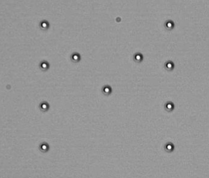
Pattern of 11 microspheres optically trapped using the time-sharing technique
Detection strategies in Optical Tweezers.
Whether a molecular, cell mechanics, or colloidal physics assay, force and position detection is necessary for any quantitative analysis of an optical trapping experiment. The following detection schemes are commonly used in commercial and custom optical tweezers configurations:
Video tracking
A basic method that utilizes high-speed cameras to track the movement of particles in real-time, providing a simple implementation and visual confirmation of trapping and manipulation. Main drawbacks are limited spatial and temporal resolution. Requires trap stiffness calibration for measuring forces.
Quadrant photodiodes (QPDs)
Detects changes in the position of the laser beam caused by the trapped particle’s movement, offering fast response time and good sensitivity for real-time tracking of particle displacements. This method is the precursor of the more advanced BFPI technique. Requires trap stiffness calibration for force measurements.
Back focal plane interferometry (BFPI)
This technique measures the interference pattern created by the trapping laser and scattered light from the particle, providing high spatial resolution and sensitivity for detecting sub-nanometer displacements and picoNewton forces. Requires trap stiffness calibration for measuring forces.
Light momentum detection
It is an improved version of the BFPI method. Based on the conservation of momentum, this method calculates forces acting on the trapped particle by measuring changes in the light beam’s momentum, suitable for dynamic force measurements offering high spatial and temporal resolution. It is a calibration-free detection method. Find more details on light momentum detection here.
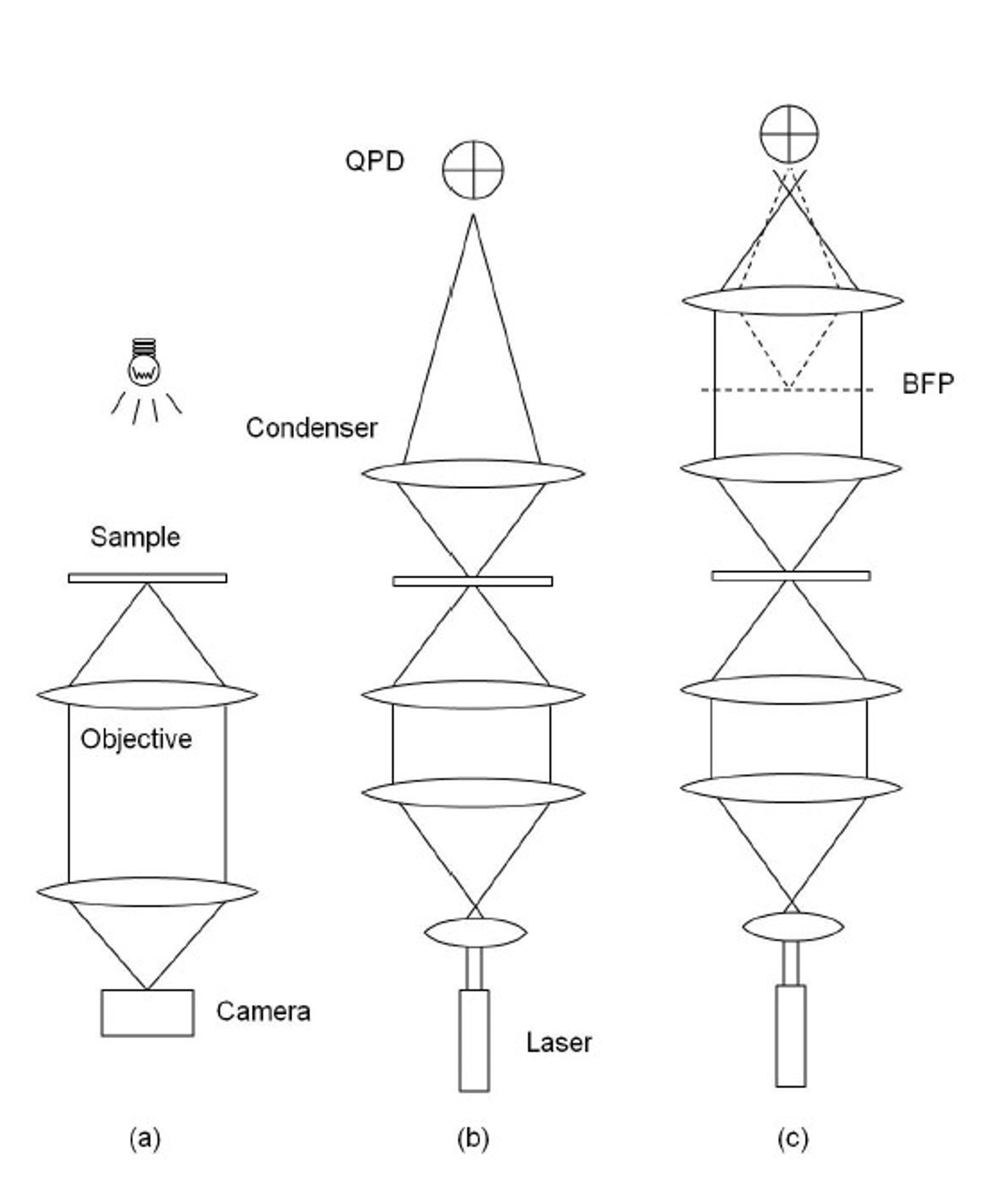
Classic detection schemes in optical tweezers: a) video-tracking, b) QPD and c) BFPI
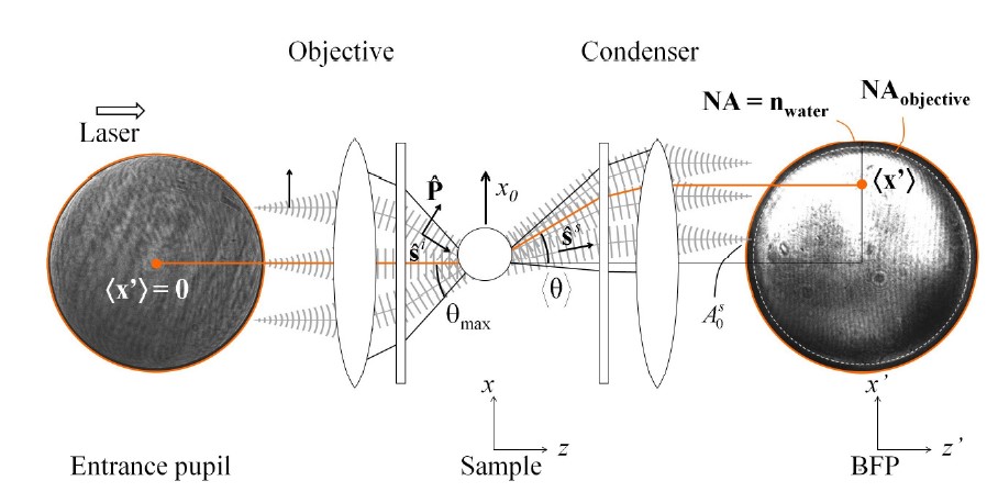
Advanced light momentum based detection sensor for optical tweezers
Trap stiffness calibration.
Calibration is essential for accurate force measurements for systems using video-tracking, QPD or standard BFPI sensors. Several methods can be used to calibrate the optical tweezers:
Power Spectrum Method
Measures the power spectral density of the trapped particle’s Brownian motion to determine trap stiffness.
Stokes’ Drag Method
Relies on moving the trapped particle at a known speed and measuring the drag force, balancing optical force and viscous drag to calculate trap stiffness.
Equipartition Method
Uses the thermal fluctuations of the trapped particle, relating the variance of the particle’s position to the trap stiffness through the equipartition theorem.
Limitations of trap calibration.
- Environmental vibrations and temperature fluctuations can affect the accuracy of force measurements.
- Viscosity variations lead to incorrect stiffness calculations.
- Requires accurate particle size knowledge for precise calibration.
- Only valid for spherical particles.
- Only valid for the the linear regime of the trap force-position curve.
- Cannot operate inside complex medium such as cells or tissues.
- Largely affected by hydrodynamic coupling with the sample glass surface.
Overcoming limitations with light momentum detection.
- Direct force measurements without relying on trap stiffness calibration. User friendly.
- Enables force measurments inside complex media outside equilibrium such as cells, tissues, organoids, embryos or liquid crystals.
- Can measure forces on irregular samples, regardless of their shape and size.
- Allows measuring beyond the linear F=k·x regime.
- Reduced sensitivity to environmental noise and viscosity variations.
- Light momentum-based detection can be performed in real-time without calibration, providing continuous data and higher accuracy throughout the whole experiment.
- Not affected by hydrodynamic coupling.
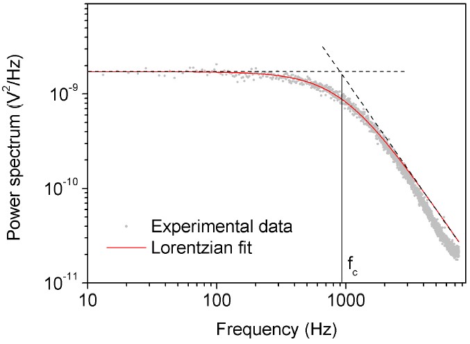
Power spectrum method used to calibrate the trap stiffness in a conventional optical tweezers setup
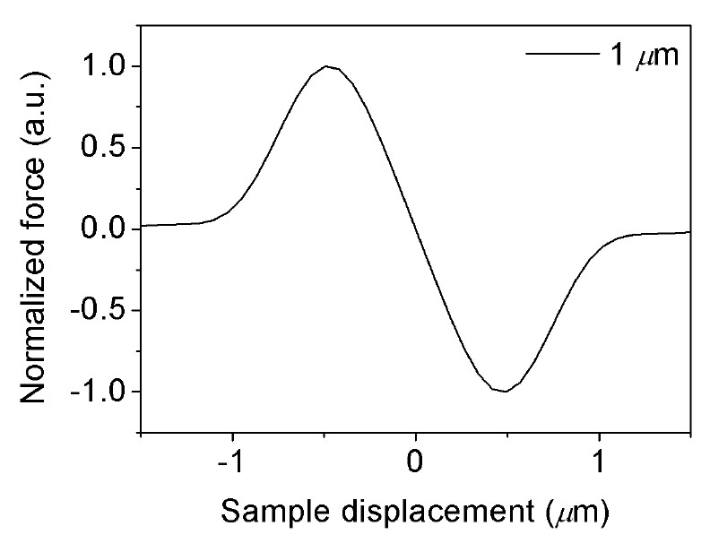
Force-position curve of an opticallly trapped microsphere
Conclusion.
Optical tweezers are a versatile and powerful tool in scientific research, enabling precision manipulation of small particles and force measurements. For complex dynamic manipulation of multiple traps, advanced beam steering techniques such as AODs or SLMs need to be implemented either using a holographic or time-sharing approach. Position and force detection schemes are necessary for quantitative analysis. Conventional detection schemes such as video-tracking, QPD or BFPI rely on trap stiffness calibration methods to measure forces which limits their implementation to certain sample and experimental conditions. The light momentum based detection method overcomes these limitations, enabling experiments in complex media in a direct and absolute way even for non-expert users since no calibration is required.
Integrating AODs technology and our unique Lunam light momentum force sensor, our Sensocell optical trapping platform extends optical tweezers capabilities into cellular environments, providing automated routines for force measurements and the mechanical characterization of cells and tissues.
Would you like a DEMO?
Download SENSOCELL brochure
